My third year project was a focus on the control of a UAV and how bird’s visual systems can be used to inspire a control method for autonomous actions.
The following is a brief overview of the work, essentially an informal summation of the final dissertation I submitted to Brunel. It will most likely be supplemented by more focused posts about more specific topics in the project.
(Disclaimer: I am by no means a computer engineer and thus learning Javascript from scratch was a tad challenging, nonetheless I am really happy with the result and i’m really looking forward to carrying on this project in my own time and hopefully next year as a masters project.)
UAVs
Unless you have been in adverse to the internet for the last year or so it is very obvious that UAV Platforms have become increasingly prevalent in recent times, even more so is the emergence of MAVs or micro air vehicles. They are currently permeating the commercial market, with startup companies utilising services such as Kickstarter to fund their projects. This is possible due to the rise of the consumer electronics market, more so the production of mobile phones, which require an integrated processors, such as the Intel Realsense capable of graphical processing and multithreading but remaining very small, cost effective and power efficient, these advances make it easy to integrate these systems into robotics applications.
Radio controlled helicopters are more representative of the toy market but the rapidly expanding smartphone market has allowed for multi-rotor toys to become more popular, with high definition cameras and the ability to be controlled via popular devices, such as iPhones or iPads. Even during the course of this project several companies have developed UAVs for the civilian market, many start-ups crowdfunded by Kickstarter, most far exceeding the goal posted;
- Zano: Produced by a British company, the Zano is “ZANO is an ultra-portable, personal aerial photography and HD video capture platform, Small enough to fit in the palm of your hand and intelligent enough to fly all by itself!”. Set to ship in July 2015 for £169.95, it is radical development in the personal UAV market, it carries a large range of transmitters and sensors, with the final goal to have a pseudo-swarming group of mini drones. The Kickstarter goal was originally set for £125,000 but reached £2,335,119, just going to show the market appeal of personal autonomous drones.
- The Pocket Drone: A tri-copter small enough to fold down to seven inches in size, touted as the first ‘personal’ drone it also features a rudimentary ‘follow me’ mode that uses GPS to track a smartphone.
- X Plus One: A novel design, which is a cross between a quadcopter and a delta wing craft, which enables it to reach 100km/h. This innovation is what is driving the quadcopter market, it is not enough to simply ship a standard ‘quad’ anymore, there needs to have element of inventive appeal to it in order to draw a sizeable audience.
Even the most cursory of Internet searches can reveal a plethora of UAV platforms ready for the civilian market. This demonstrates the commercial viability of these systems, as the technology becomes more available, it also becomes more popular. This popularity and affordability has enabled anyone to purchase such a device and fly it the same day with no licence. Because of this, more legislators are moving to control the use of drones, arguing that without adequate training, users could lose control and cause damage or property or other people. Some manufactures have implemented GPS locks which are hardcoded into the drone as to stop it flying above specified air space, Heathrow for example, had a drone flown just 20ft away.
There is an issue, however, if the drone loses GPS control, which is where an autopilot system would take control of the drone and attempt to guide it safely to the ground. Quadcopter limitations are mostly due to their battery life and payload carrying capacity, therefore it is important to optimise the amount to equipment the system uses to function in order to reduce weight to allow for a larger mission payload capacity and longer flight duration under battery power. Using computer vision and lightweight, power efficient cameras it is possible to equip a UAV system with the tool required to navigate a space and react to its surroundings. This negates the need for more power intensive and heavier systems such as LIDAR, which, although more accurate a medium must be found for which these machines are correctly tasked and utilised according to their respective limitations and capabilities.
Inspiration
Biomimetics, the term coined by Otto Schmit 1950s, is defined as taking inspiration from nature and implementing it into design and has been happening for thousands of years. Great artists and engineers such as Da Vinci and the Wright Brothers took inspiration from animals, the logic being that nature has got it correct. Therefore when designing a mechanism deigns found in the natural environment should be copied or adapted. This approach has led to some great human achievements such as planes, humanoid robotics, and micro UAVs. The inspiration behind visual control of a UAV comes from observing the flight of birds, their visual control mechanisms when looking for prey or avoiding obstacles in flight and landing and applying them to a control system, mechatronic and computer vision problem.
It is this approach that has been applied to many areas of science, from computing, such as Conway’s ‘The Game of Life’ a simple evolutionary mathematical simulation based on simple rules of life and death which can simulate evolution itself, to BMT Group’s SHOAL, an autonomous swarming fish project for inspection of harbours, and even Velcro’s inspiration came from hooked structures in nature such as burs. DARPA funded company Boston Dynamics recently acquired by Google, takes inspiration from nature in their robotics work, humanoid robots such as Petman and Atlas are bipedal and use joints very similar to humans for locomotion, another application where the biomimetic process can be seen is the LS3, Big Dog, Wildcat, Cheetah and Spot robots. Upon seeing images and video of the platforms at work it is immediately apparent that the joint structure of the legs and the gait used is very much inspired and modelled after nature’s evolutionary work developed over thousands of generations of animals, selecting the best assets and attributes via natural selection.
For the majority of birds, eyesight is their most important asset, and so it is important to not only understand how birds view the world around them but also to understand how they process sensory information.
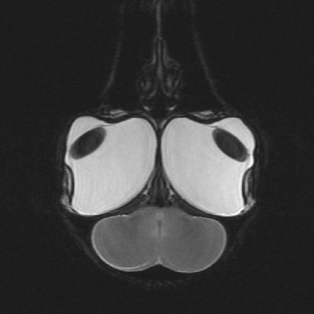
Above is an MRI scan of a golden eagle’s head, it shows that the eyes take up a significant portion of the bird’s head and are even larger than the brain. Eyesight is the bird’s primary method of hunting prey, finding a mate and navigation and so they have evolved to utilise this asset to its fullest potential. As different birds use visual information for different reasons, numerous species and a mixture of predatory and non-predatory birds must be examined in order to garner a thorough understanding of the different strategies employed and to use that information in this project to implement into a control and computer vision strategy.
Below is a brief overview in how birds use certain methods to see and understand the world around them and how they create parallels to computer vision methods:
Edge Detection
It is important to understand how birds perceive objects and use the process of edge detection in order to land and navigate large distances. Edge detection plays a very large role in the identification of objects in computer vision, and will feature in this project. The most pertinent work (I will post the full bibliography once I am able to, which will be around July) I found while researching this was Edge Detection in Landing Budgerigars (Melopsittacus undulatus’) which states that:
“We conclude that budgerigars use visual edges to target and guide landings. Calculations of photoreceptor excitation reveal that edge detection in landing budgerigars is performed by a color-blind luminance channel…Since a visually contrasting edge is likely to represent the edge of an object, it would be a favorable place to land, as it would offer the bird’s claws a good grip at the point of touchdown.”
Colour blind edge detection is used in computer vision extensively, and most commonly envelop segmenting an image to a 2D colourspace, i.e. black and white. This is commonly used to identify certain images in a cluttered space, and for this application will be used by the Parrot AR.Drone’s firmware to identify a roundel.
Colour Vision
Bird’s colour vision is something to be jealous of, most species can see into the Ultraviolet spectrum, allowing them to track prey’s trails of urine on the ground from high above. But what colour do bird’s respond to most? Zeigler and Bischof in their book Vision, Brain, and Behavior in Birds states “By far the most abundant cone pigment in every bird species examined is the long-wavelength form of iodopsin, which absorbs at wavelengths near 570nm.” _This corresponds to the spectral region occupied by the red-green wavelengths, showing that most birds will respond to those colours. Birds _use this ability to find and identify food
“Berries and fruits develop a highly reflective waxy coating as they ripen. On the other hand, most green leaves do not reflect UV light. So even if a red berry seems quite visible against a green leaf to human eyes, for birds this contrast is enhanced.”.
Colour Segmentation is pivotal to this project, as the drone will respond to an object that is red to avoid it, using HSV colourspace segmentation to allow robustness even in differing lighting conditions.
Optical Flow
Birds typically use optical flow for navigational purposes. In addition to edge detection, optical flow in Budgerigars was also studied by Bhagavatula et al. in [Optic Flow Cues Guides Flight in Birds](http://www.cell.com/current-biology/abstract/S0960-9822(11) where birds were studied flying through narrow corridors with horizontal and vertical stripes on the walls.
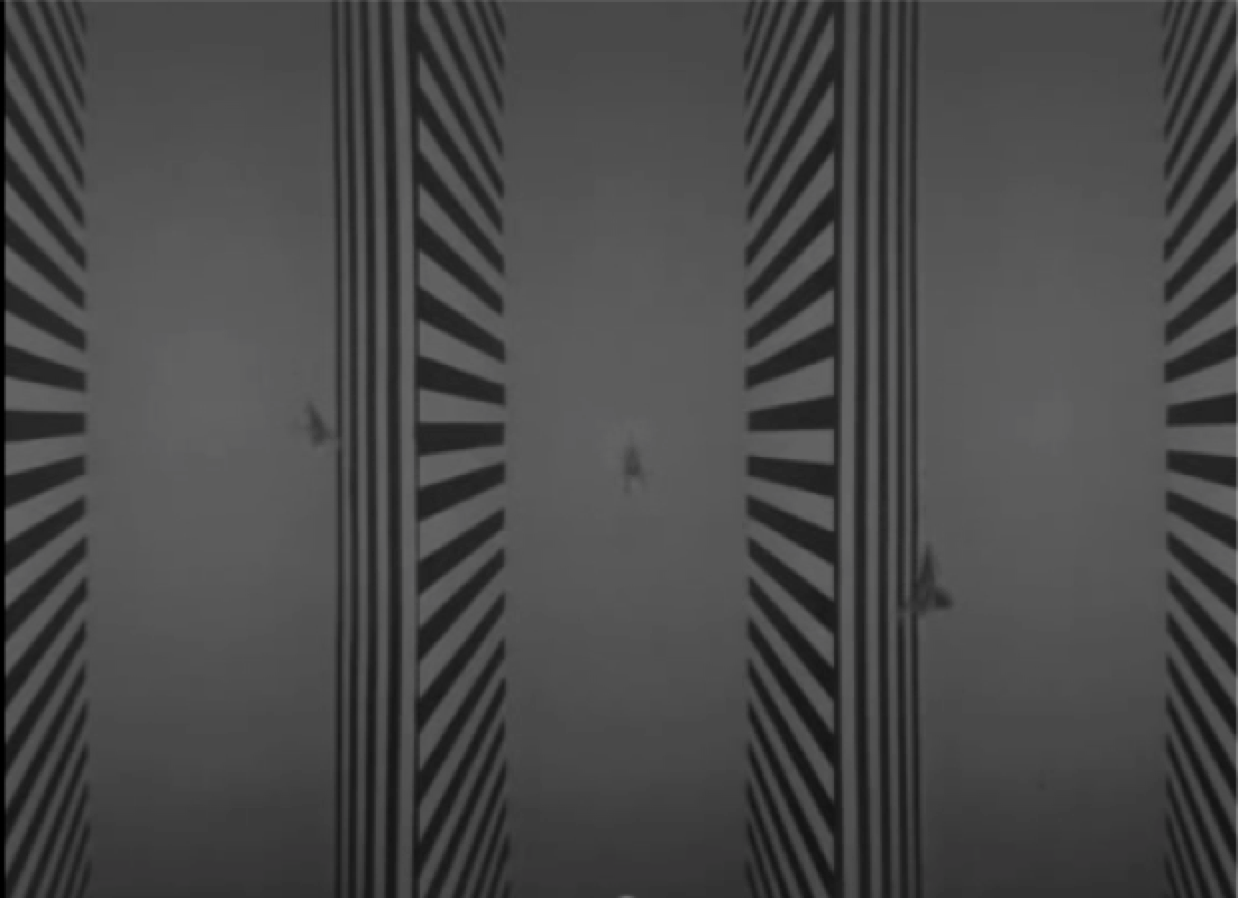
These findings can give fantastic insight into how birds can navigate densely cluttered environments such as woodland, which could then be applied to UAV control. “These results indicate that budgerigars negotiate narrow passages by balancing the velocities of image motion (optic flow) that are experienced by the two eyes”, using their binocular vision and large field of view they are able to regulate speed and distance using optical flow cues from perceived image motion in their environment. For more information feel free to follow the link above.
The use of optical flow and flicker fusions frequency was studied by Dr Kane in her study of Goshawk hunting strategies: “The goshawk flew to intercept targets by fixing the prey at a constant visual angle, using classical pursuit for stationary prey, lures or perches, and usually using constant absolute target direction (CATD) for moving prey. Visual fixation was better maintained along the horizontal than vertical direction.” It was found that goshawks will keep their target as close to the centre of their optical flow field as possible to track their prey and make a clean kill, it was found that a sudden bolt to the side could lead to the prey evading the bird.
Optical Flow is used in UAVs, especially by Parrot, they use a downwards facing, low resolution, high frame rate camera to compare keypoints on the ground to estimate the velocity of the ground in relation to the drone and thus allow it to steady itself in flight and detect the roundel using the same camera.
Simulations
Lots of simulations were done using MATLAB’s fantastic computer vision toolkit including Edge detection, corner detection, colour segmentation and blob detection. They gave me a benchmark of how much computing time and power were require for each method and what would be practical to apply to the drone.
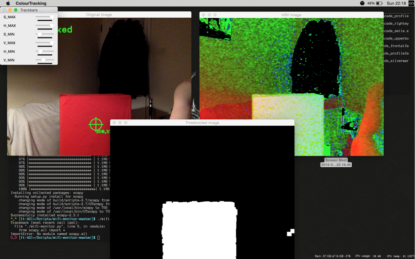
I also used an OpenCV tutorial and C++ to hack together a very basic HSV (Hue Saturation and Value) colour segmentation program that used the webcam, this allowed me to dial in the correct HSV values for the red obstacle after testing it with different lighting conditions.
Application
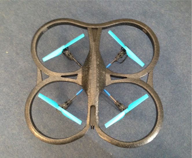
So the next step was to apply this stuff to a UAV, the Parrot AR.Drone was a good choice and the wifi control allows the use of a computer ground station without too much bother, and already has reliable stabilisation and control firmware, which meant that I wouldn’t have to worry too much about that stuff myself.
Getting Airborne and Autonomous
The AR.Drone SDK and ROS didn’t seem to play well with the 2008 MacBook with 32 Bit Ubuntu 14.04 I was originally using before the great hard drive failure of 2015, and so I looked for alternative solutions, I stumbled across the Nodecopter project, using Node.JS to send and receive the UDP commands required by the AR.Drone. It was also about this time that the drone was lovingly dubbed ‘Damon’.
Node.JS
I would like to start this section by saying that Node.JS totally kicks ass, the amount of data and events it can handle is amazing and made it great for this purpose. 10/10 would use as a ground station to UAV communication client again.
The AR.Drone SDK is in the process of being ported to Javascript by Felix Geisendörfer, this combined with the Ardrone_Autonomy module created by Laurent Eschenauer, (who also led me in the right direction for getting my PID under control for which I am very grateful), which I edited and tweaked to fit my needs, allowed control of the drone via a Javascript file which could be run in the console with a .png stream to a canvas element in a browser and control via the keyboard:
 //keyboard -------------------------
 var keypress = require('keypress');
    keypress(process.stdin);
    //killswitch
    var quit = function() {
        console.log('Quitting....attempting to land safely.');
        process.stdin.pause();
        drone.stop();
        drone.land();
        drone._udpControl.close();
        process.exit(0); // this cleans everything up without the unsightly error codes when quitting
    }
    process.stdin.on('keypress', function(ch, key) {
        if (key &&; keys[key.name]) {
        keys[key.name]();
    }
    if (key && key.ctrl && key.name == 'c') {
        quit();
    }
 });

 //keys -----------------------------

 process.stdin.setRawMode(true);
 process.stdin.resume();
 keys = {
    'space': function() {
    console.log('Takeoff!');
    drone.takeoff();
 },
    'l': function() {
    console.log('Land!');
    drone.stop();
    drone.land();
 },

 //and so on ...
The keyboard control was found to be absolutely necessary before advancing to any kind of autonomous control a hand had to be kept on the killswitch at all times or else the drone would inevitably do AWOL and cause all sorts of havoc.
You can also force the drone into a hover state, with roundel following (I like to call it lost puppy mode) as such:
 'h': function() {
    drone.stop();
    drone.config('video:video_channel', 3); //bottom camera
    drone.config('control:flying_mode', 2); //hover over roundel and orient, lost pup
    console.log('Hovering...');
    ctrl.zero(); // zero the controller
 },
And a video of it in action:
(As mentioned before the full code and install instructions will be posted in due course, as well as more in depth posts going into far more nerdy detail.)
Computer Vision and Autonomy
So now to meat and potatoes of the project, avoiding objects based on colour information, all the while maintaining steady, controlled flight. How hard can it be? Well apparently for a novice such as myself, pretty darn tricky. But I go there in the end, here’s the gist of it:
Using the firmware of the AR.Drone and the node modules, the drone would be able to take off, locate the roundel with its lower camera, declair a stable hovering state. Following this it would use the front facing camera, locate a red object, then decide which would be the quickest way around it, as shown here.
An overview of the program structure is here.
To use the computer vision methods, the program would have to sample the video feed from he drone as .png images, thankfully this can be easily done with the ‘drone-png-stream’ script that comes built with the node-ardrone module. This data would also be fused with the ‘Navadata’ sent by the firmware to gain a state estimate and move accordingly.
The Testing Environment
So the testing environment was by no means ideal. There was limited space and with a solid blue carpet floor it gave very poor optical flow for the drone’s camera, which the code was taking data from. It was also hotter than the sun and had no thermostat. Nevertheless you make do with what you can get your hands on as an undergrad student.
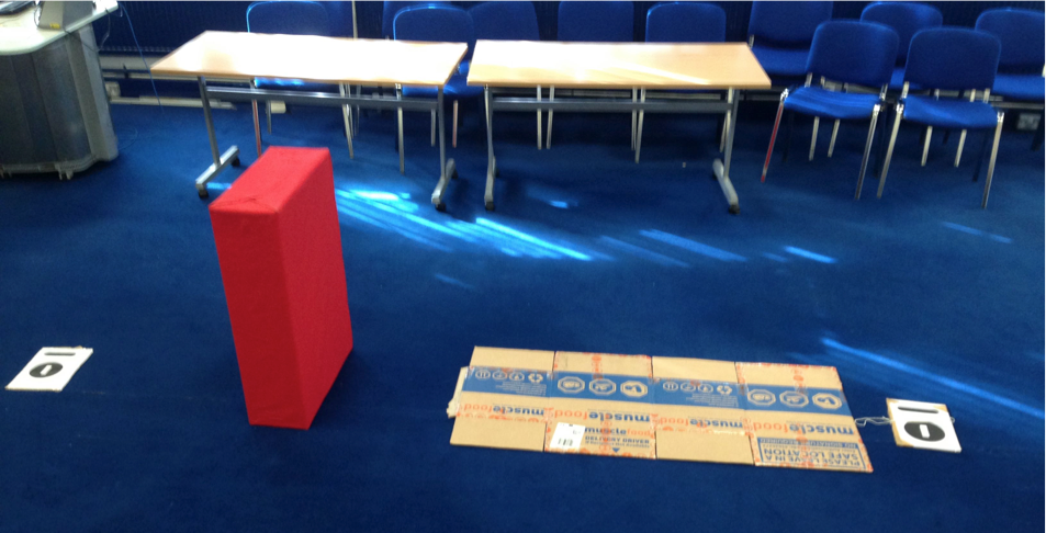
Your eye may be drawn to the box on the floor this maked a decent replacement for an optical flow surface. The roundels on either side would be moved about depending on where I wanted the drone to start and finish the mission.
Results
So did it actually work? Yep! Damon could detect a red object, decide if it was large enough to get in its way and if it was, move around it, I was stoked. However it is still very much proof of concept baby steps at them moment and I would have liked to get more functionality and adaptability out of the code and have the drone track the box when moving either side so it could avoid different shapes but the time spent on the great hard drive calamity annoyingly didn’t leave time, but it does give me something to work on over summer.
PID
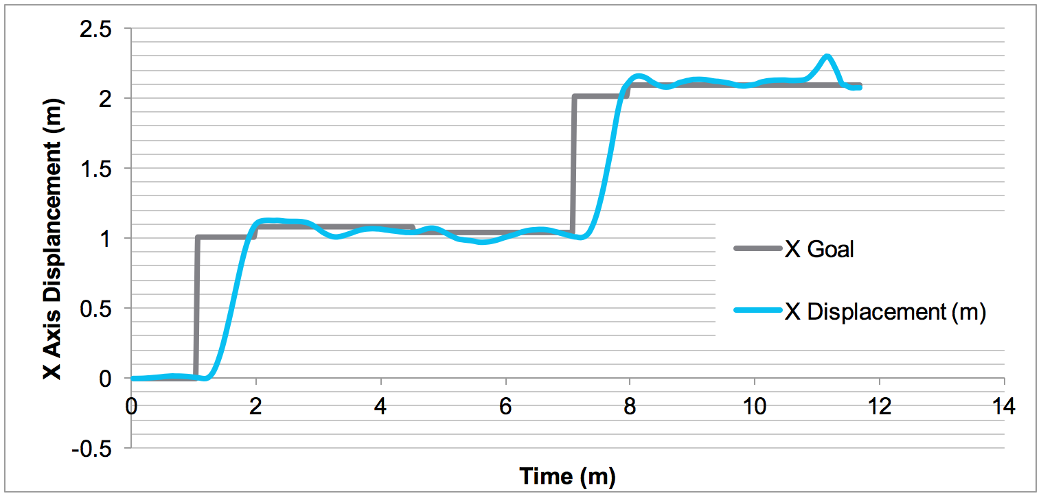
The following are the results of tuning the 4 PID controllers for X Y Z and Yaw, well Z and Yaw actually had to be PD controllers in the end to avoid the drone losing its mind if anything untoward happened. It sought comfort by flying as high as possible apparently.
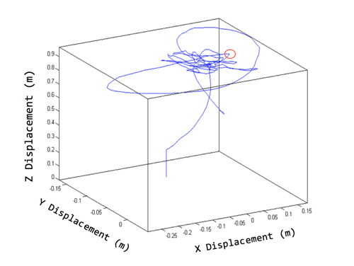
The PID was tested by programming the drone to hover over the roundel and stay there no matter what, even if I gave it a sharp shove, it should then return back to the roundel with minimal overshoot as quickly as possible, using the telemetry on board to calculate the error and correcting it as PID controllers are so very good at doing.
Here is an early development test video:
And now for some nerdy graphs using the MATLAB 3D plotting tool and the telemetry form the drone, I could plot the drones flight in virtual 3D space, the red circle indicated where the push was made, you can see the drone overshoot slightly and settle back in place over the roundel.
The new PID was also used to move the drone as the Ardrone_autonomy modules allows, however I was testing my modified code and so I had to check how my changes had affected the characteristics, I was willing to sacrifice some rise time for as little overshoot as possible as the blue carpet made any error compound into a horrific ‘fly by wire’ nightmare.
Object Detection and Avoidance
After many many manifestations of the code and many more crashes, the code was working and I was happy to write up what I had achieved.
The drone would move forwards until it detected an object with the correct amount of red pixels to declare it as an object, following this a decision has to be made by the drone in order to navigate the obstacle. This was achieved by nesting ‘if’ loops inside the colour space function. The amount of red pixels in the image is sampled, and if it it above a certain threshold, the decision making code will take over from any of the other mission elements (emergency land will still work), and perform appropriate action.
Here is the video of the first time the drone moved over the box:
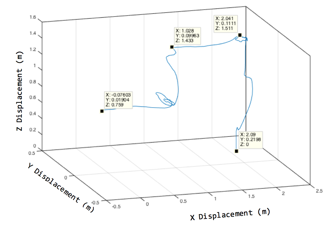
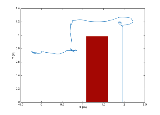
The following graph is a map of the flight data from a mission where the drone avoided the obstacle by moving over it and landing again. The flight moves from left to right, the approximate dimensions of the box have been drawn in to give a better indication of the environment and the accuracy of the drone.
Here is the result of setting the PID stabilisation declaration timer and as many intermediary delays to as little as possible. It did perform the task faster but it looked like it had had a few bevs.
A similar example was set up, however this time the setup would be ‘blind’, so in this case the drone was manually positioned over the roundel, facing away from the target and then the roundel was rotated so the drone would face the red target, and simulate an environment that was new to the drone as it could not track any red pixels until it was turned around, the drone was instructed to hover at approximately 50cm from the floor so it would be flying level with the centre of the red box.
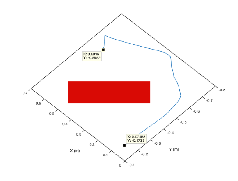
In this instance the drone decided the most optimal route would be to move right around the box, it is also possible to see where the drone identifies the roundel on the other side of the box, as it can be seen to move backwards sharply. Here is the video from a similar test.
To Conclude
So there it is, it’s not much but I’m damn proud of it. Feel free to get in touch if you have any questions or suggestions.